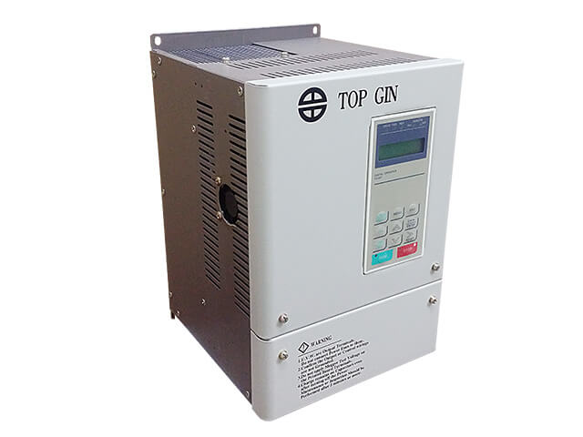
TG1000 high frequency inverter
/
Model: TG1000
Inverter
【Performance】
● High frequency inverter
[TG600 Current Vector Inverter] [TG700 Servo Controller IP] [TG900 Variable Load Drive]
- TG1000 inverter control the torque output through the precise torque limit function. In case that any breakdown happens, it may ensure the safe operation and prevent from any impact. TG1000 inverter evidences its durability and perfect performance in the application of heavy-duty machine
- TG1000 inverter features its full-speed and highly-precise operation even under the condition of load change.
- Persistent-speed control from light to heavy load
- Speed detection rate ± 0.2%0-100% load
- For continuous operation with high torque in low speed, please use Top Gin professional inverter.
[About TOP GIN] [TOP GIN Milestones] [TG100 Mini Type Inverter] [TG300 Pan With Drive]
[TG600 Current Vector Inverter] [TG700 Servo Controller IP] [TG900 Variable Load Drive]
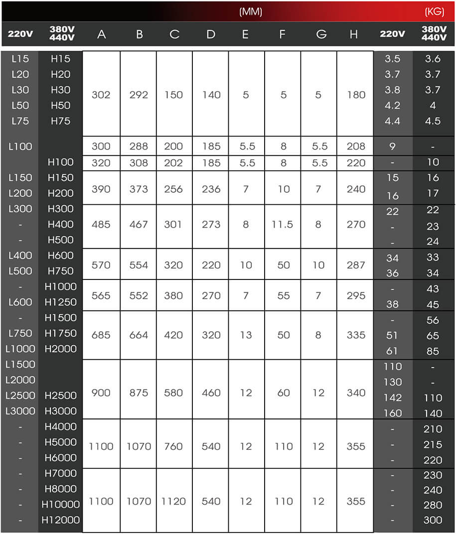
【Specification】
|
Output characteristics |
Standard 220 class |
L15 | L20 | L30 | L50 | L75 | L100 | L150 | L200 | L300 | L400 | L500 | L600 | L750 | L1000 |
|
Motor (KW) |
0.75 | 1.5 | 2.2 | 3.7 | 5.5 | 7.5 | 11 | 15 | 22 | 30 | 37 | 45 | 55 | 75 | |
|
Inverter capacity (KVA) |
2.3 | 2.5 | 4.3 | 6.8 | 9.9 | 13.5 | 19.5 | 24.5 | 37.5 | 51 | 62 | 70 | 85 | 110 | |
|
Rated output current (A) |
6 | 8 | 11 | 18 | 26 | 34 | 50 | 65 | 96 | 132 | 163 | 183 | 224 | 330 | |
|
Motor rated current (A) |
3.3 | 6.2 | 8.5 | 14 | 19.6 | 26.6 | 39.7 | 53 | 77.2 | 105 | 131 | 160 | 190 | 260 | |
|
The maximum output voltage |
Three-phase 200~240V (corresponding to input voltage) |
||||||||||||||
|
Reated output frequency |
1300Hz | ||||||||||||||
|
Power supply |
Reated onput voltage and frequency |
Three-phase 200~240V 50/60Hz |
|||||||||||||
|
Allowable voltage fluctuation |
+10%,-15% | ||||||||||||||
|
Allowable frequency fluctuation |
±5% | ||||||||||||||
|
Output characteristics |
Standard 380/440 class |
H15 | H20 | H30 | H50 | H75 | H100 | H150 | H200 | H300 | H400 | H500 | H600 | H750 | H1000 | H1250 | H1500 | H2000 | H2500 |
|
Motor (KW) |
0.75 | 1.5 | 2.2 | 3.7 | 5.5 | 7.5 | 11 | 15 | 22 | 30 | 37 | 45 | 55 | 75 | 90 | 110 | 160 | 185 | |
|
Inverter capacity (KVA) |
2.6 | 3.7 | 4.7 | 6.7 | 12 | 16 | 21.5 | 26 | 41.5 | 52 | 62 | 75 | 98 | 130 | 160 | 170 | 230 | 260 | |
|
Rated output current (A) |
3.4 | 4.8 | 6.2 | 8 | 14.5 | 21 | 28 | 34 | 54 | 67 | 80 | 98 | 128 | 165 | 206 | 224 | 300 | 340 | |
|
Motor rated current (A) |
1.6 | 3.1 | 4.2 | 7 | 9.8 | 13.3 | 19.9 | 26.5 | 38.6 | 52.3 | 65.6 | 79.7 | 95 | 130 | 156 | 190 | 270 | 310 | |
|
The maximum output voltage |
Three-phase 345~480V (corresponding to input voltage) |
||||||||||||||||||
|
Reated output frequency |
1300Hz | ||||||||||||||||||
|
Power supply |
Reated onput voltage and frequency |
Three-phase 380~440V 50/60Hz |
|||||||||||||||||
|
Allowable voltage fluctuation |
+10%,-15% | ||||||||||||||||||
|
Allowable frequency fluctuation |
±5% | ||||||||||||||||||
|
Control characteristics |
Control mode |
V / F control |
||||||||||||
|
Starting torque |
120% / zero rpm |
|||||||||||||
|
Speed control range |
1: 100 |
|||||||||||||
|
Speed control accuracy |
± 0.2% |
|||||||||||||
|
Speed response |
5Hz (200ms) |
|||||||||||||
|
Torque limit |
0.01 to 3600 seconds (acceleration, deceleration time set individually) | |||||||||||||
|
Torque Control |
Four-quadrant operation(Motorize forward / reverse, Motorize backward / reverse) |
|||||||||||||
|
Torque response |
40Hz (25ms) ( 20Hz (50ms) without PG ) |
|||||||||||||
|
Frequency control range |
0.01~1300Hz |
|||||||||||||
|
Frequency control accuracy (temperature change) |
Digital signal: ± 0.01% (-10 ℃ ~ + 40 ℃) Analog signal: ± 0.1% (25 ℃ ± 10 ℃) |
|||||||||||||
|
Frequency setting resolution |
Digital signal: 0.01Hz Analog signals: 0.03Hz / 60Hz * (12bit) |
|||||||||||||
|
Frequency output resolution |
0.01Hz |
|||||||||||||
|
Overload capacity |
150% of rated current for 1 minute PER10MIN @ 40 ℃ above |
|||||||||||||
|
Analog frequency setting signal |
DC-10~+10V,0~10V(20KΩ)4 ~ 20mA(250Ω) |
|||||||||||||
|
Acceleration and deceleration time |
0.01 to 6000.0 seconds (four groups of acceleration, deceleration time set individually) |
|||||||||||||
|
Brake torque |
Approx. 20% additional brake up to 150% |
|||||||||||||
|
Run / stop setting |
Operator, RS232, RS485 / 422, the control circuit terminals, 12/16 Bit binary signal |
|||||||||||||
|
Protective function |
Motor protection |
Electronic thermal relay protection, phase failue protection |
||||||||||||
|
Instantaneous overcurrent |
Stop at approx.200% of rated output current |
|||||||||||||
|
Fuse FusingProtection |
The motor stops running after the fuse blows |
|||||||||||||
|
Overload |
The motor stops running if 150% of rated output cirrent at 1 minute PER 10MIN @40℃ |
|||||||||||||
|
Overvoltage |
220V-The motor stops running if the DC voltage of the main circuit is over 400V |
|||||||||||||
|
Low voltage |
220V-The motor stops running if the DC voltage of the main circuit is over 200V |
|||||||||||||
|
Instantaneous power-off offset |
The motor continues running after blackouts in 2 seconds(external capacitor) |
|||||||||||||
|
Overheat |
Thermocouple Protection |
|||||||||||||
|
Stall prevention |
Stall prevention during acceleration and deceleration |
|||||||||||||
|
Ground protection |
Electronic circuit protection |
|||||||||||||
|
Charging indication |
The charging indicator turns on when the DC voltage of the main circuit is over 50V |
|||||||||||||
|
Vibration |
Below 20Hz 1G, 20 ~ 50Hz: 0.2G |
|||||||||||||
|
Efficiency |
Pf≧0.95&η≧0.95@40℃ above |
|||||||||||||
(Download specification of Inverter TG1000)
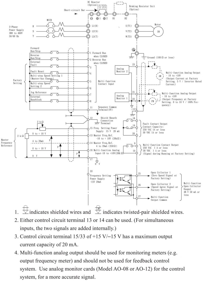
【WIRNG】
● Below is connection diagram of the main circuit and control circuit. Notify the terminal number when wiring.
.jpg)
【CONNECTION DIAGRAM】
● The inverter standard diagram below only requires main circuit terminal (R, S and T are for power input; U, V and W are for motor input) for digital operator.
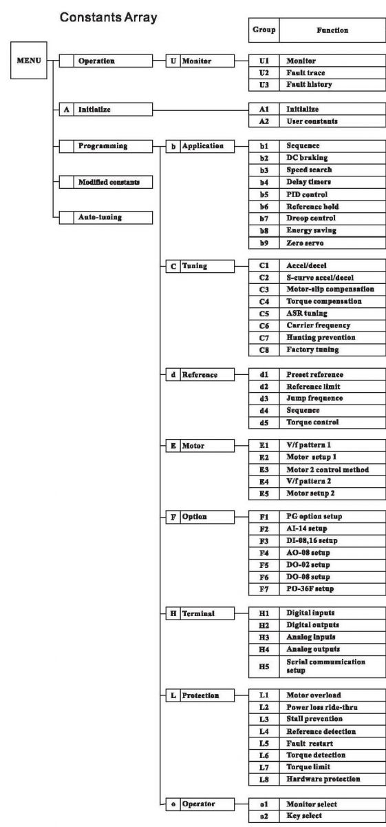
【CONSTANTS LIST】
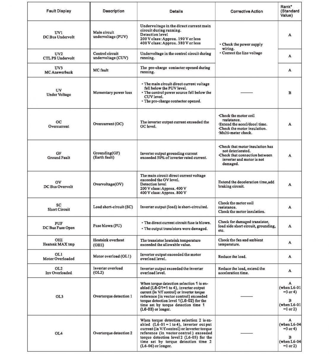
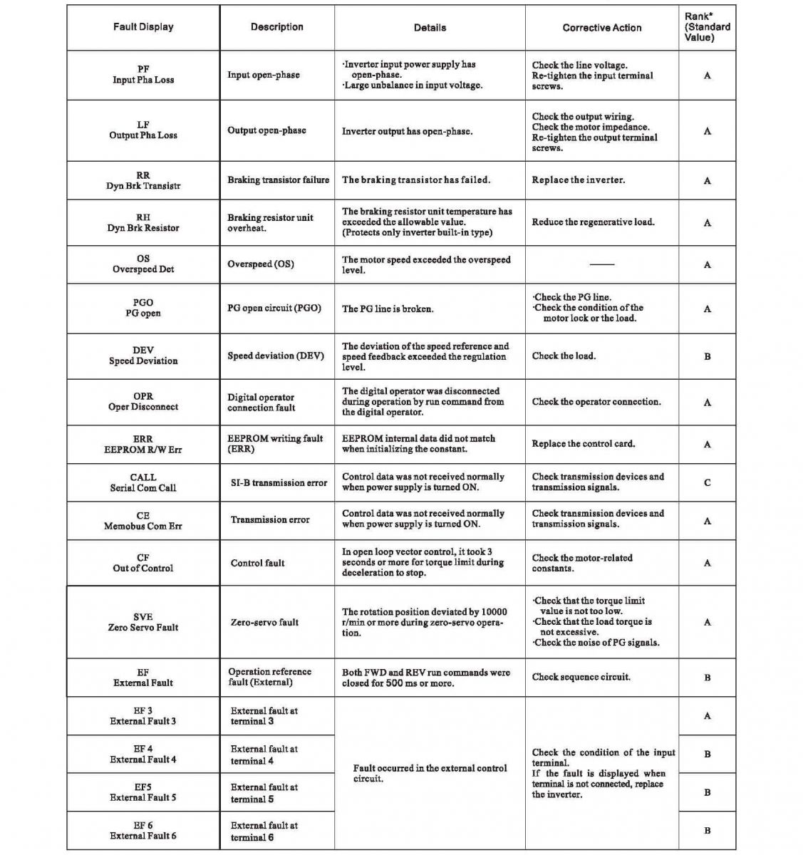
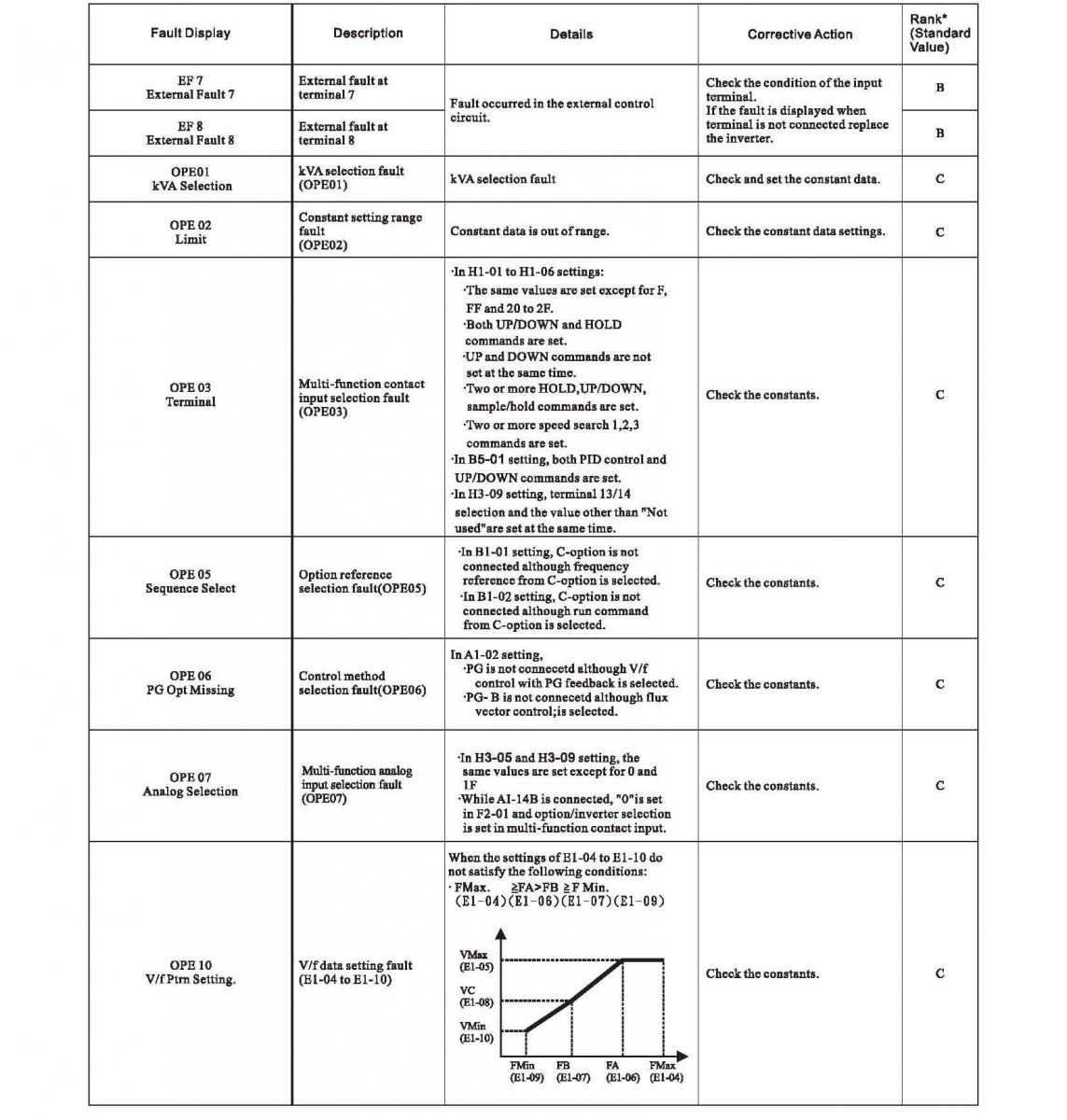
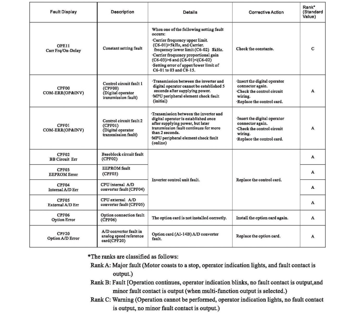
【FAULT DIAGNOSIS AND CORRECTIVE ACTIONS】
(Download manual of Inverter TG1000)
.jpg)