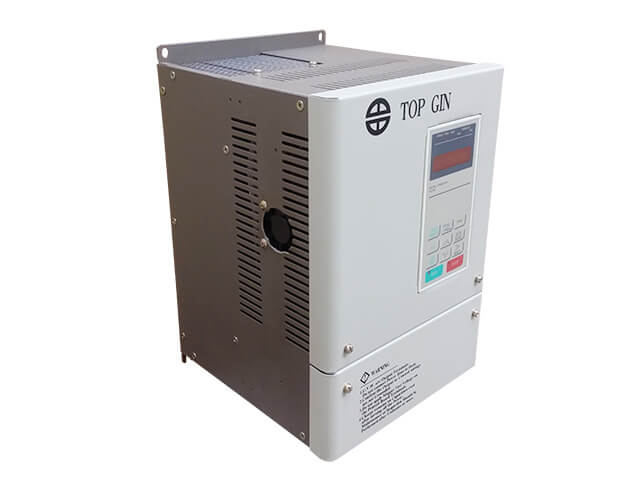
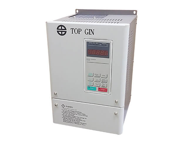
TG700 servo controller IP
/
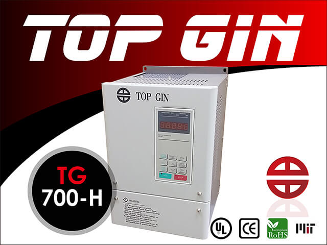
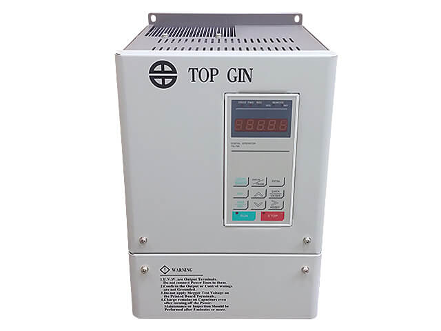
Model: TG700
Inverter
【Performance】
● Starting torque compensation (way of inputting the load detection value)
● Blackout management control
● Multi-speed operation (the maximum is 9 speeds)
● Automatic zigzag acceleration and deceleration operation
[TG600 Current Vector Inverter] [TG900 Variable Load Drive] [TG1000 High Frequency Inverter]
- TG700 servo controller IP contains starting torque compensation (way of inputting the load detection value)
- Blackout management control (operating with storage battery)
- Multi-speed operation (the maximum is 9 speeds)
- Automatic zigzag acceleration and deceleration operation
[TG600 Current Vector Inverter] [TG900 Variable Load Drive] [TG1000 High Frequency Inverter]
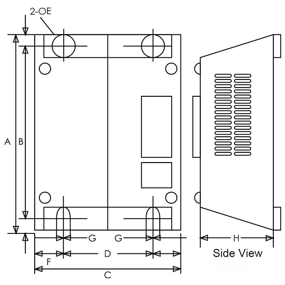
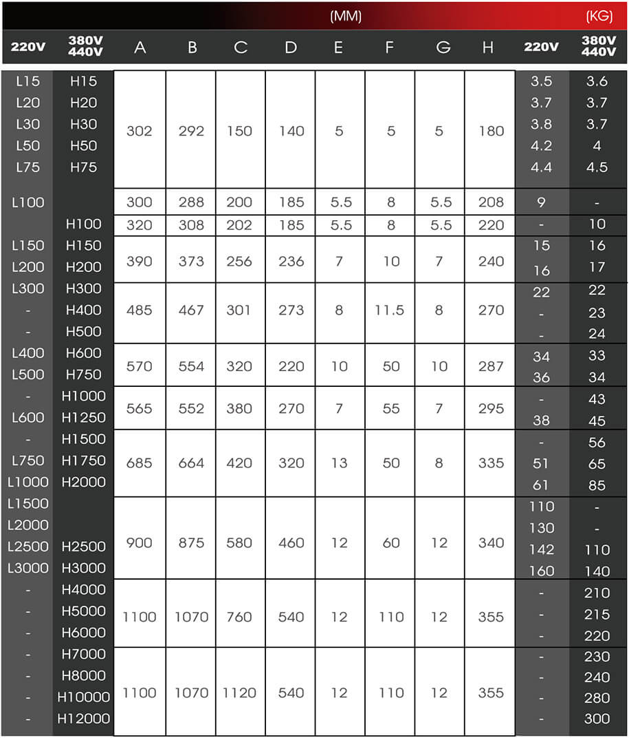
【Specification】
|
Output characteristics |
Standard 220 class |
L15 | L20 | L30 | L50 | L75 | L100 | L150 | L200 | L300 | L400 | L500 | L600 | L750 | L1000 |
|
Motor (KW) |
0.75 | 1.5 | 2.2 | 3.7 | 5.5 | 7.5 | 11 | 15 | 22 | 30 | 37 | 45 | 55 | 75 | |
|
Inverter capacity (KVA) |
2.3 | 2.5 | 4.3 | 6.8 | 9.9 | 13.5 | 19.5 | 24.5 | 37.5 | 51 | 62 | 70 | 85 | 110 | |
|
Rated output current (A) |
6 | 8 | 11 | 18 | 26 | 34 | 50 | 65 | 96 | 132 | 163 | 183 | 224 | 330 | |
|
Motor rated current (A) |
3.3 | 6.2 | 8.5 | 14 | 19.6 | 26.6 | 39.7 | 53 | 77.2 | 105 | 131 | 160 | 190 | 260 | |
|
The maximum output voltage |
Three-phase 200~240V (corresponding to input voltage) |
||||||||||||||
|
Reated output frequency |
400Hz | ||||||||||||||
|
Power supply |
Reated onput voltage and frequency |
Three-phase 200~240V 50/60Hz |
|||||||||||||
|
Allowable voltage fluctuation |
+10%,-15% | ||||||||||||||
|
Allowable frequency fluctuation |
±5% | ||||||||||||||
|
Output characteristics |
Standard 380/440 class |
H15 | H20 | H30 | H50 | H75 | H100 | H150 | H200 | H300 | H400 | H500 | H600 | H750 | H1000 |
|
Motor (KW) |
0.75 | 1.5 | 2.2 | 3.7 | 5.5 | 7.5 | 11 | 15 | 22 | 30 | 37 | 45 | 55 | 75 | |
|
Inverter capacity (KVA) |
2.6 | 3.7 | 4.7 | 6.7 | 12 | 16 | 21.5 | 26 | 41.5 | 52 | 62 | 75 | 98 | 130 | |
|
Rated output current (A) |
3.4 | 4.8 | 6.2 | 8 | 14.5 | 21 | 28 | 34 | 54 | 67 | 80 | 98 | 128 | 165 | |
|
Motor rated current (A) |
1.6 | 3.1 | 4.2 | 7 | 9.8 | 13.3 | 19.9 | 26.5 | 38.6 | 52.3 | 65.6 | 79.7 | 95 | 130 | |
|
The maximum output voltage |
Three-phase 345~480V (corresponding to input voltage) |
||||||||||||||
|
Reated output frequency |
400Hz | ||||||||||||||
|
Power supply |
Reated onput voltage and frequency |
Three-phase 380~440V 50/60Hz |
|||||||||||||
|
Allowable voltage fluctuation |
+10%,-15% | ||||||||||||||
|
Allowable frequency fluctuation |
±5% | ||||||||||||||
|
Control characteristics |
Control mode |
High carrier wave, sine wave PWM, vector control |
|||||||||||||
|
Frequency control range |
0.1~ 400Hz | ||||||||||||||
|
Frequency accuracy (temperature change) |
Digital signal: ± 0.01% (-10 ~ + 40 ℃) Analog signal: ± 0.1% (25 ℃ ± 10 ℃) |
||||||||||||||
|
Frequency setting resolution |
Digital signal: 0.1Hz Analog signals: 0.06Hz / 60Hz |
||||||||||||||
|
Frequency output resolution |
0.01Hz | ||||||||||||||
|
Overload capacity |
150% of rated current for 1 minute |
||||||||||||||
|
Analog frequency setting signal |
DC 0~+10V (20KΩ),4-20mA(250Ω) | ||||||||||||||
|
Deceleration time |
0.01 to 3600 seconds (acceleration, deceleration time set individually) |
||||||||||||||
|
Brake torque |
About 20% (125% loaded brake controller) |
||||||||||||||
|
V / F curve |
Select from 15 types of fixed V/f patterns or set any V/f pattern. |
||||||||||||||
|
Protective function |
Motor protection |
Electronic thermal relay protection |
|||||||||||||
|
Instantaneous overcurrent |
More than 300% of rated output current |
||||||||||||||
|
Fuse FusingProtection |
The motor stops running after the fuse blows |
||||||||||||||
|
Overload |
150% in one min., 200% in ten sec. |
||||||||||||||
|
Overcurrent |
220V-Stops when main-circuit DC voltage is approx. 400V |
||||||||||||||
|
Low voltage |
220V- Stops when main-circuit DC voltage is approx. 220V |
||||||||||||||
|
Instantaneous power-off offset |
Setting when playing power outages than 15ms motor free run to stop |
||||||||||||||
|
Overheat |
Thermistor protection |
||||||||||||||
|
Stall prevention |
Stall prevention during acceleration and deceleration |
||||||||||||||
|
Ground protection |
Electronic circuit protection |
||||||||||||||
|
Charging indication |
The charging indicator turns on when the DC voltage of the main circuit is over 50V |
||||||||||||||
|
Environment |
Venues |
The room is not corrosive or dusty places |
|||||||||||||
|
Ambient temperature |
- 10 ~ + 50 ℃ |
||||||||||||||
|
Storage temperature |
- 20 ~ + 70℃ | ||||||||||||||
|
Humidity |
Below 90% RH (non-condensing conditions) |
||||||||||||||
|
Vibration |
20Hz below: 9.81 M/S (1G), 20 ~ 50Hz :1.96M/S (0.2G) |
||||||||||||||
|
Protective structure |
Wall Mount locking plate inside and take pay type |
||||||||||||||
(Download specification of Inverter TG700)
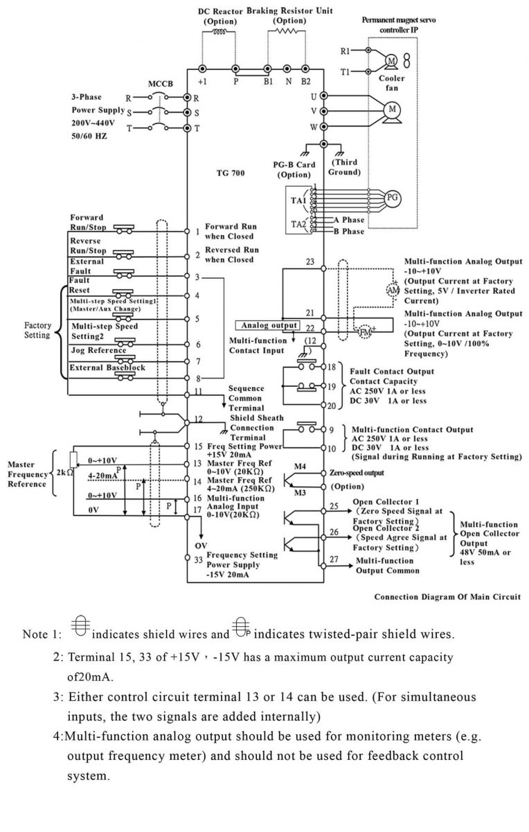
【WIRNG】
● Below is connection diagram of the main circuit and control circuit. Notify the terminal number when wiring.

【STANDARD CONNECTION DIAGRAM( TG700 TYPE)】
● Electric machine with PG wiring by using braking unit and braking resistor unit
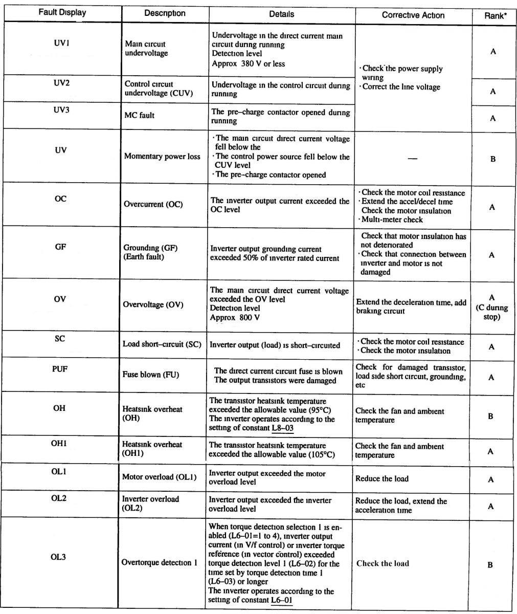
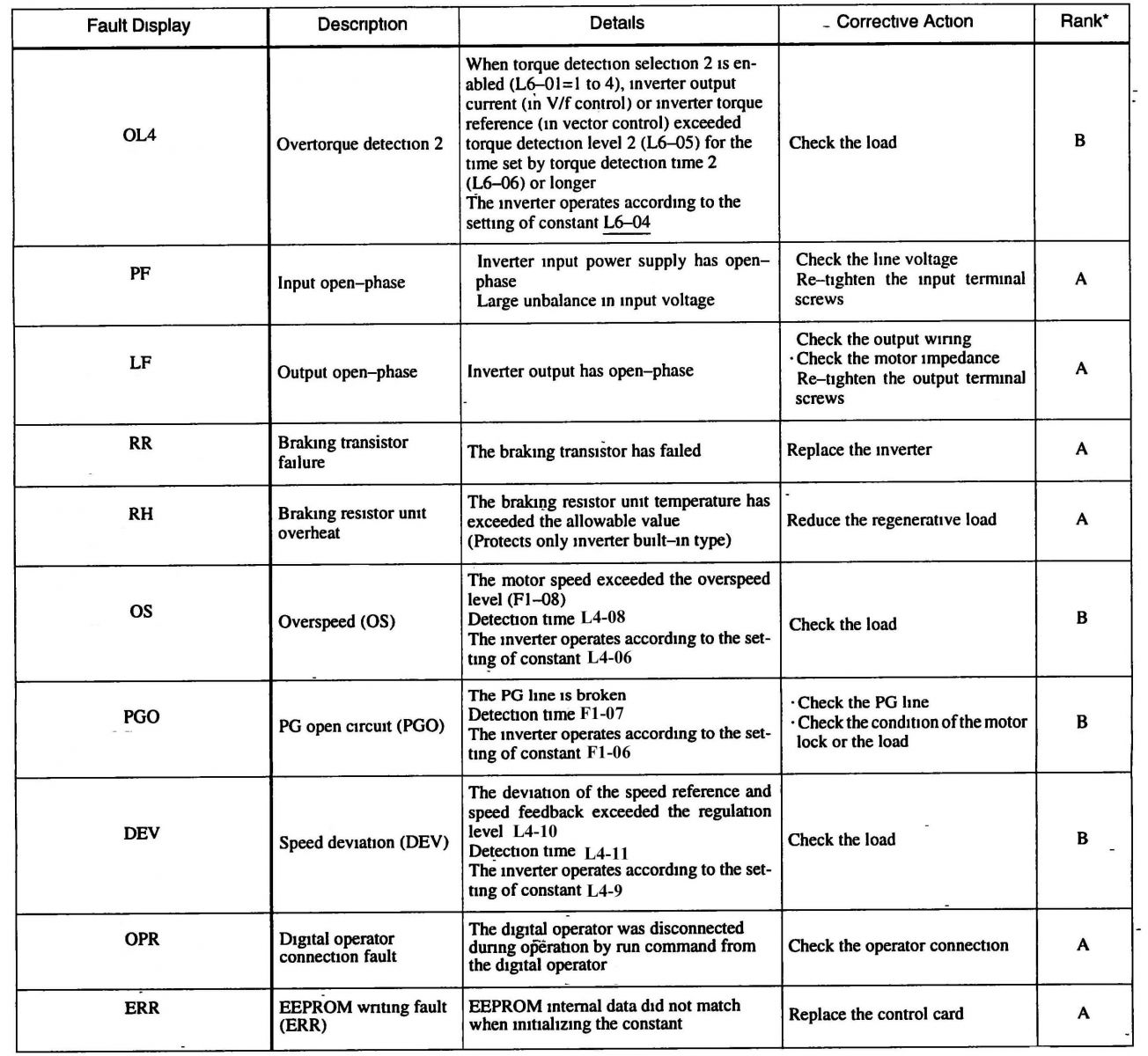
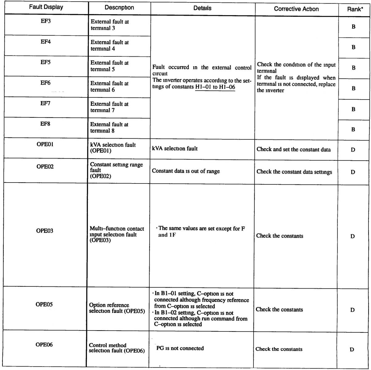
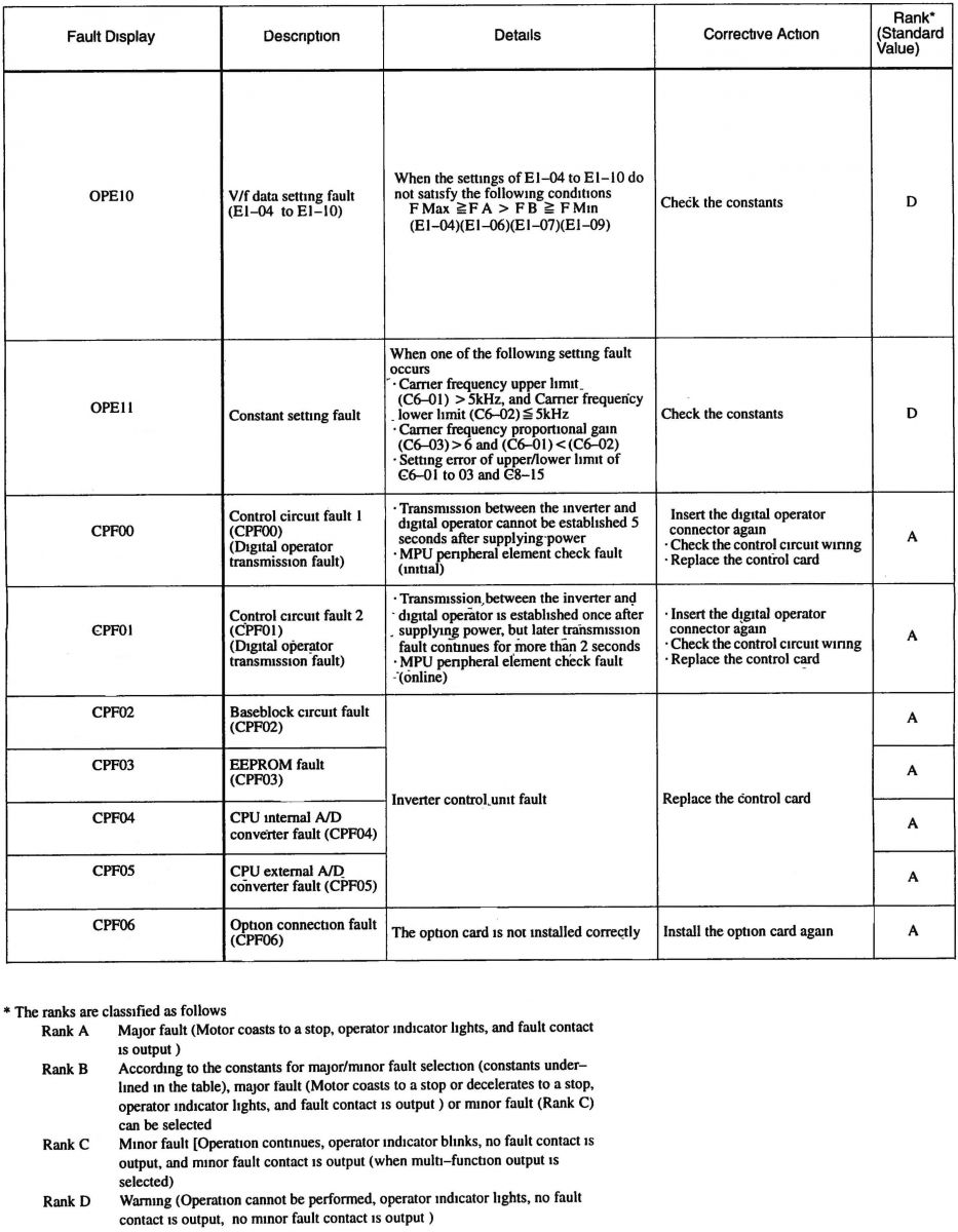
【FAULT DIAGNOSIS AND CORRECTIVE ACTIONS】
- TG700 servo controller IP fault display and the fault contents caused by motor/machine mal-functions and the corrective actions to be taken.
- When TG700 servo controller IP detects a fault, the fault is displayed on the digital operator and actives the fault contact output and the motor coasts to a stop. Check the cause in the table below and tack the corrective actions.
- If the inspections or corrective actions described cannot solve the problem, contact Top Gin representative immediately.
- To restart, turn ON the reset input signal or depress [>RESTART]key or shut OFF the main circuit power supply once, to reset the stop status.
(Download manual of Inverter TG700)